Tuesday, March 31, 2015

Creating 3D .PDFs from .IFC files

      Here is a small tutorial showing how to turn your 3D Revit models into the .PDF format. This could be useful for collaborating on ideas, and showing potential clients your 3D model in a program they may have installed on their computers. I have read about various ways to open your Revit models with Adobe reader, but until now, none of them have worked as I wanted.
The first thing you need to make sure of, is that you have Adobe Acrobat 9 Pro Extended installed. A 30 day free trial is available here. This was the original problem I had when trying to create 3D .PDFs in the past. Unfortunately Adobe have removed the functionality from the newest version,  but I'm sure it's still possible to get a copy of the software somewhere.
Once you have all the correct software installed, open up your .RVT file and follow these simple steps:
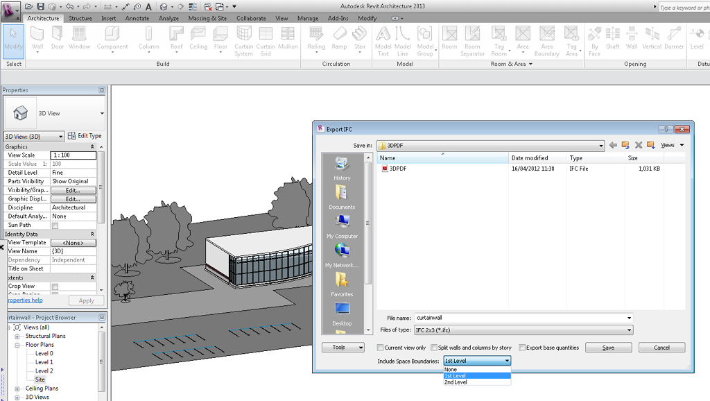
Click on the Revit icon and select Export > IFC – Here you will be given a number of different options, as shown in the image below. Make sure you select which levels you want visible as well as other options such as splitting walls and columns by story. Finally select the .IFC export type.
uploaded image
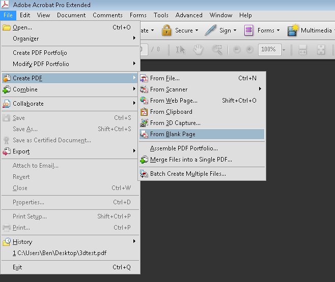
After you have exported your .RVT file into the .IFC format, you will need to open up Adobe Acrobat Pro Extended. Next you will want to create a blank page PDF as shown in the image below. File > Create PDF > From Blank page.
uploaded image
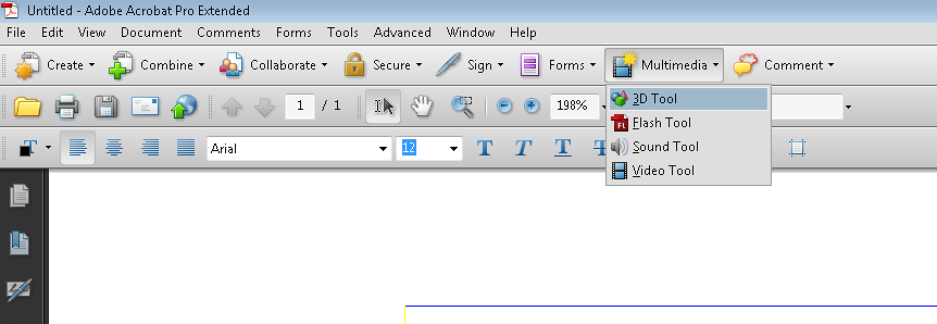
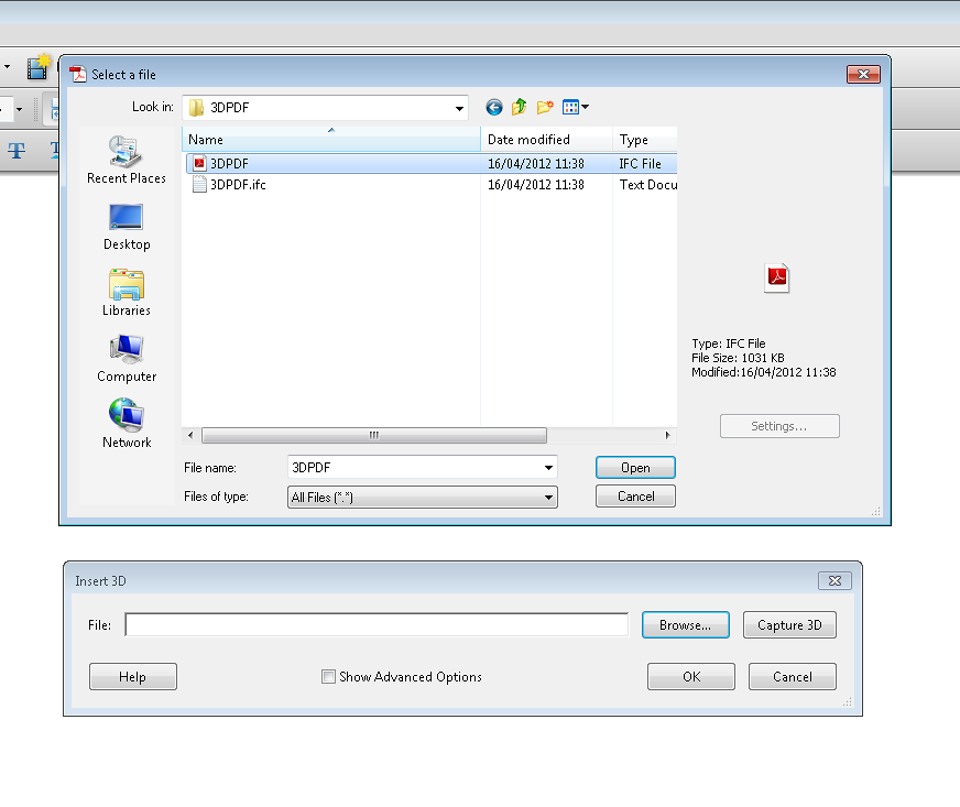
After you have done this you will need to use some of the tools in Acrobat pro insert your 3D .IFC file. To do this, simply click on the 'Multimedia' icon on the ribbon as shown below. Select the 3D Tool, and sketch a box on the blank page where you want to add your model. I would recommend drawing a large box covering the whole page, depending on the size and detail required.
uploaded image
Now a pop up box will appear asking for the location of your 3D file as shown in the image below. Simply locate your .IFC file which you saved earlier from your Revit model on your hard drive and select 'Open'.
uploaded image
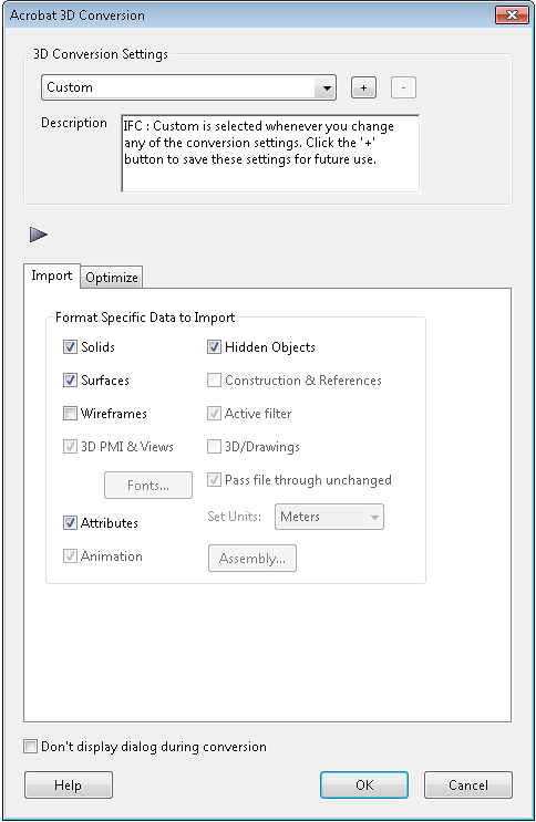
Once you have selected your .IFC file you will be able to set some custom conversion options. In this window just consider what you want shown in your model. I have choosen to remove the wireframe option as it will only be for visualisation purposes. It is also possible to increase or decrease the quality of your 3D .PDF here. This will of course influence the size of the file.
uploaded image
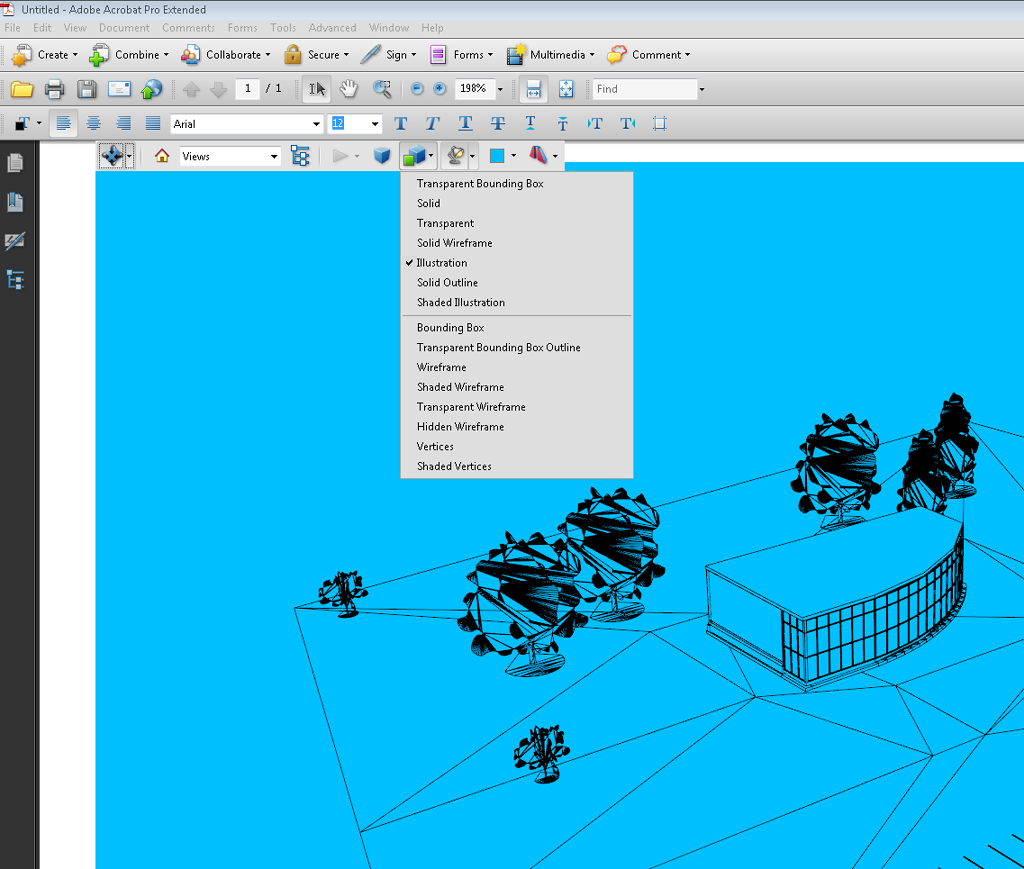
Once you have set up your conversion options, you will see your 3D model as a still image on your .PDF document. You are now able to save your original 3D Revit model as a .PDF file. Once you have saved your file, there are also other options which you can play around with. As you can see in the image below, I have selected an 'Illustration' option, and selected a background colour. For a default 3D view, it is best to select the Solid option. You will now be able to zoom, in and out of the model, as well as panning and rotating.
uploaded image
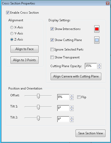
Finally, an additional option which I thought was pretty smart, is the option to change the view. As default, Acrobat 9 Pro will set cross sections on levels which you created in your Revit model. It is also possible to create new sections of the model, which could come in useful if you wanted to show furnishings or even single building elements. The image below shows the 'cross section properties' where you can modify and create new cross sections in your model.
uploaded image
All in all I think this is a cool, and unexpected task to be able to perform for a .PDF file. Most of the time these kind of files are associated with text and images, but this more interactive 3D version would be very useful, if only Adobe released it as standard on all their .PDF readers. I hope this post has helped someone trying to create a .PDF file from their Revit model.

Thursday, March 26, 2015

Revit 2D Details Part 4 - Linking 2D and 3D

2D detail is standalone and not connected with any part of the model. This scenario is ideal for details like typical partition details and door details.

If you are used a Callout View, you will have overlaid your detail on the 3D model. What if the underlying elements of the 3D model move? The detail will look a little messed up and uncoordinated. This can be ok as it will be a prompt to make some necessary changes to deal with the changes to the underlying model but can be a little frustrating if the changes are relatively minor and things don't line up.


The original detail.

The RC wall in the mode is moved but the 2D elements remain at the same location.

To ensure the plaster and the partition always align with the RC wall, do the following:

1. Add all the elements to a Group which I introduced in the second post. Once you select a number of 2D elements, you will see the Create Group under Create on the Modify | Lines panel. If you miss any elements, simply select the Group and select Edit Group whereby you will have an option to add or remove elements.

2. Select the Align tool from the Modify panel. Underneath the ribbon you will see some options. The Prefer option allows you to set the preference for which part of the wall can be selected. Select Wall faces as we want to align the face of the RC wall with the back of the plaster.


3. Select the a face of the RC wall first as we want to align to this.
4. Select the back face of the plaster.
5. You will now see a padlock which is open. Click on the padlock to lock it.

6. Do the same again for the left hand side of the RC wall.


Now the back face of the plaster is aligned on 2 sides with the RC wall. You can test this by moving the RC wall.

Revit 2D Details Part 3 - Organising and Reusing Details

How many of us had grand plans to reuse details? Probably most designers or organisations. This may have taken the form of A3 folders of typical details or individual PDF and/or CAD files in shared folders which are organised in some wonderful system of folders and sub-folders. How many were maintained? Likely very few. Details are rarely as typical as we think. Regulations and Standards change. Sometimes details aren't as good in practice to build as they looked on paper and changes happen that do not get incorporated into the final details. Design and Build contracts leave designers creating design intent details rather than detailed designs as some of the construction or products being incorporated are likely to change. BIM may just be the opportunity to get organised again. If managed effectively, Revit offers a solution which is quite effective to solving the library of details.

Insert 2D Elements from File

Revit provides an Insert 2D Elements feature which allows you to select a Revit project file and then presents you with a list of Callout and Drafting views only. The Insert 2D Elements from File is located on the Insert panel.


After selecting a Revit file, you will be presented with a list of Views. Not al views are presented, only the views that are 2D which are Callout and Drafting views. If you tick the Transfer view Scale box, your view will inherit the scale of the imported view which is likely what you want in most cases.


All the 2D entities including lines, regions, groups, text and insulation will be copied into the current view. 3D objects will not, so you may need to do a little modification depending on how similar the arrangement of your current detail is to the inserted detail.

Lots of Details

Hopefully, eventually you will ave lots of great details. Wouldn't it be great to put them all in one place. You can export multiple views to a single Revit file. Click the Application menu (the big R on the top left hand side), select Save As -> Library -> View.

Note: This function can export any type of view.


After selecting the Views you wish to export, click OK and select a folder and file name.

If you wish to import any or all of the views, on the Insert panel, select Insert Views from File. This is a similar dialog box to export. Then select the views you want to import.


A reasonable strategy here would be to export the views from a project file to a temporary Revit file and then import them back into a Revit file with all your typical details.

Note: It is very important that you name your views appropriately. If you are looking through a bunch of details, detail at column is almost meaningless. Be reasonably explicit with view names e.g. Partition to Column plan detail.

There is one more piece of functionality that Revit has that CAD does not. It is a fully formed database and you can utilise this to help sort the views in your details library. I lightly touched on project Parameters in the Title Blocks post. Project Parameters can be used to help you sort your details.

On the Manage panel, select Project Parameters. If you are starting from scratch you may have none. Click Add.


We are going to add a parameter that is of type 'Project Parameter' and it will accept text and be available to Views.

  • Name: For this example, use 'Package' as the name.
  • Type of Parameter: Select Text as the type of Parameter. Similar to spreadsheets or database fields, there are many different formats for the field.
  • Group parameter under: Select Text. The group you add it to is up to yourself. This affects the category it is placed into on the properties palette and can be changed if necessary afterwards.
  • Categories: Select Views only as the Category. This will ensure that the parameter appears in the Properties palette for Views.


I have included 3 text parameters for Views.


Now, remember from the first Sheets post, you can sort and filter by parameters. Try sorting by Package. You can sort by Package and then by Fire Rating or sort by Package and filter by 1 Hour Fire Ratings.


The Project Parameters will be also exported using the Save As -> Library -> View so it is important that you set-up Project Parameters in you template file as early as possible. You can add as many parameters as you need, but be logical about it. Think about how you would search for details rather than how you wish to categorise them as searching is what they are being created for. A Package parameter based on a classification system is important. Use your national or governing bodies coding system e.g. Uniclass or Omniclass. You could also include parameters for Detail Status, Approved By, Date Approved, etc. in order to add a level of quality assurance.

Revit 2D Details Part 2 - Editing Tools

You should spend a little time making details look good as they look good and are easy to read. Details imported from CAD will need to work, especially to tidy up hatches and text. Revit includes great tools for drawing in 2D. Some of these are the very same annotative tools that were used to create the title block.

The tools which include:
  • Detail Line - draws lines of varying line styles
  • Regions -  There are two types of regions, filled and masking region. Filled regions are akin to hatching in AutoCAD and Masking Regions are akin to wipeouts.
  • Components - smart objects that can repeat e.g. bricks, metal studs.
  • Detail Group - like blocks, items can be grouped together.
  • Insulation - a tool to create insulation.

Detail Line

There is an important note before I begin on Lines. I spent years trying to convince users to use polylines instead of lines and now there is no polyline in Revit.Revit does have some editing tools that allow you to select a chain of lines which gives you a little more flexibility that you get with polylines.

Revit lines are quite basic and simple. You select Detail Lines from the Annotative panel, select a Line style and draw. The line styles can be edited or changed in the Manage panel under Additional Settings. I will cover settings in detail in a separate post but you can use the built in line styles which are Thin Lines, Medium Lines, Heavy Lines and Hidden Lines which should be adequate for most purposes.

Regions

To create a filled region, select Filled Region from the Region button on the Annotative panel. The default pattern will be the last one used. You can select another from the pull-down list on the Properties palette, or create a new pattern by clicking on Edit Type.


If you have completed the Title Block exercise, duplicating and editing types should now be familiar. Click the Duplicate button.


Name the new type 'Skimmed Plaster' and select Sand - Dense as the Fill pattern. Notice that there are two pattern types, model and drafting. Drafting is used for 2D views and scale according to the scale of the view whereas Model patterns have a consistent scale regardless of the view scale e.g. 100x100 grid used for tiles.


Skimmed Plaster is now you default Filled Region pattern. You can now draw the area bounding the skimmed plaster and the filled region will be applied when complete.

If you are using a pattern which requires orientation such as cross hatch, you have 3 options which are very useful.
Align with Element - The pattern will try to align with the boundary.
Orient to View - the pattern with align with the view it is in.
Keep Readable - The pattern will align to the bottom or right hand side of the sheet that the view is placed in.


Masking Region is straight forward. There is no type, it just simply masks anything behind it. You can adjust how much to the front the mask is using the Arrange tools on the modify panel. These are very similar to desktop publishing or document applications.

Tip: The typical Filled Region types that you use regularly should be included in your template to avoid rework and ensure consistency.

Components

Components are very useful for repeating items which occur a lot in construction e.g. metal studs in partitions, bricks, blocks, purlins on a roof truss, etc. Revit comes with a number of out of the box components to get you started. There are 3 types of components.

Detail Component
Detail Components are similar to blocks in AutoCAD in that they are a number of basic objects such as lines and arcs grouped into one object. In Revit Detail Components are really 2D families and can include some dynamic features such as mirroring.

Repeating Detail Component
Effectively the same as Detail Components but includes an array feature which is extremely useful for recurring items such as metal studs, purlins, etc. Like many other objects in Revit, you can select another type from the properties pull-down list and change the type by clicking Edit Type. If you need a metal stud @600 c/c and another @300 c/c, then these will be 2 different types. use the Duplicate button to create another type.

The layout determines how the objects are spaced. The options are:

Fill Available Space - All objects will touch and fill up the space e.g. brickwork.
Fixed Distance - all studs will be a specified distance apart.
Fixed Number - A number of objects which you can specify in the Properties palette will be created within the length you specify.
Maximum Spacing - Metal studs or floor joists are a good example, you want one at the start and end and then have them spaced evenly between at a maximum spacing.


Legend Component
This is a feature for legends which I will cover separately.

Additional components can be loaded by using the Load Family button from the Insert panel. You will find the 2D families in Libraries\Country\Detail Components. The location in Revit 2013 is Libraries\Country\Detail Items. I am not sure why they changed the name of this folder from 2012 to 2013.

The UK libraries are organised by the CAWS system and the US is arranged by the Omniclass system. There are over 800 generic 2D details available which a lot of users don't realize they have. You can create and build up your own library too. You can use the Metric or Imperial Detail Component Family Template to start a new Detail Component. I feel another Post coming on.


Detail Group

A detail group is very similar to group in Microsoft Word except that you give each Group a name. Objects grouped together can be edited or ungrouped. The editor is not dissimilar to the block editor in AutoCAD. In the editor you can add or remove objects that are outside the group which is quite smart.
Detail Groups are very useful for collections of objects that repeat e.g. toilet layout, angle bracket with fixing, etc.

Insulation / Batting

Insulation is reasonably straightforward but a useful tool that was lacking in AutoCAD. There are 2 simple properties:

  1. Insulation Width - the width of the insulation
  2. Insulation Bulge to Width Ratio - If set to 1, the insulation bulge will be the same with as the insulation, if set to 3 then it will be a 1/3. A ration of 3 looks right to me.

Conclusion

The Detail Component feature alone is ample evidence that Revit is in fact better at 2D detailing than CAD systems. The next and last post on 2D Detailing will look at integrating a reference plane to tie in some parameters of details to the 3D model and I will also look at the reuse of 2D details so that you can manage and build a useful library that can be easily accessed by your design teams.

Revit 2D Details Part 1 - Introduction

A common misconception about BIM is that it is all 3D, BIM doesn't do 2D details and isn't all our investment in 2D CAD being washed down the sink hole. Not so. Revit can do detailing better than AutoCAD plus it can import your CAD details so you don't have to redraw everything.

Why is Revit better at detailing?

One simple answer - Coordination. Revit numbers, names and links everything in a tightly coordinated manner plus it has two great methods to incorporate 2D details.
  1. Drafting View - A Drafting View is a standalone view specifically set up for 2D details. A Drafting View is not linked to any other view in Revit but does have the benefits in that the 2D Detail view can be incorporated into sheets. Drafting Views are useful for details that are not referenced to another view e.g. typical 1 hour fire rated partition detail.
  2. Callout View - A Callout View allows you to reference a detail on a plan, elevation or section e.g. parapet detail on 1:25 section. A detail tag is placed on the plan, elevation or section which links to the Callout View.

How do I get an CAD detail into Revit?

Fom the View panel, select either Drafting View or Callout View. If you have selected Drafting View, you will be prompted to give the View a name and select the appropriate scale. Both can be changed later. Revit will create the View which will be a Drafting View type. The view will initially be empty.


If you have selected Callout View, a Callout symbol will be placed on the current view. You will need to place it a set the size of the box which will define the extents of the view. The label can be placed by selecting the box and then dragging the nodes. Open the View by right clicking on the Callout symbol and select 'Go to View'. The View will initially contain a subset of the referenced view defined by the Callout box.


You can stretch this and the Callout symbol will adjust accordingly. Set the scale to a desired detail scale e.g. 1:2 and set the Detail level to Fine.


Notice the Callout symbol on the referenced view does not yet have a number or a sheet reference. Drag the detail view into a sheet and Revit will automatically number the detail and include the sheet number. You can change the Detail number in the properties palette. The Detail number must be unique though and Revit will warn you if you try to renumber a detail to the same number used for another detail.


Note: When you place the view on a sheet, the View Name will be used as the title for the view. You can use the The Title on Sheet property to override the View name, but it is good practice not to do this.


Now import a 2D drawing by selecting Import CAD from the Insert panel. Select a 2D CAD file. make sure you select Black and White as the color and tick the Current View only box.

Note: To save time, the CAD drawing should only contain the detail you are importing. If the drawing contains numerous details, you will have to delete the other details, so it will save time and effort if the CAD detail you are importing contains the minimal amount of information.
Hatches don't import into Revit, they just end up as lines. If you are in a hurry, you can lave them in and delete and replace them with Regions afterwards, but otherwise delete them in the CAD file.


If you are using a Callout view, you can move the entities to align with the Revit model view. Use the align tool to accurately place the 2D detail. Once you have aligned your imported detail to the correct location, you can hide some or all of the Revit entities if required. On the example below, I have hidden the partition from the model by selecting the partition, right clicking select Hide in View and then select Element. I kept the RC Wall visible.


The location of the grid bubbles can be adjusted by dragging them. This will not affect the referencing view. Moving the grid lines would though.You may need to tidy up some of the text by setting the width appropriately or combining text into a single text item.

For relatively little effort, your CAD details are now integrated into Revit and benefit from the great coordination tools in Revit.

Tuesday, March 24, 2015

Parameters Part 5 - Types and Project Units

Type of Parameter

When you create a Project or Shared parameter, you must assign a type. Remember I selected Text for the Fire Performance parameter. Text is the most flexible type as it can include virtually any value. But with flexibility comes some responsibility and some restrictions. In the 4th Post on schedules, I used the equals and does not equal comparison operators to check if the value of the parameters met specific conditions e.g. does not equal FD30. This works well for text provided that there is consistency in the parameter values i.e. all 30 minute rated doors are FD30. Note - For text type parameters, Revit will make an effort to compare any values and give a result i.e. A is greater than 9 as far as Revit is concerned.

If you want more explicit values, you need to select a type of parameter other than text. For example if we wanted to compare the area of a room against the brief area, we should use Area as the Type of Parameter. This will allow us to compare like with like and do smart things like getting the difference between the two areas using subtraction. Text might do this but if someone enters 300 sq.m instead of 300, Revit will treat the value as text and will not do the subtraction. By using the Area type, we also ensure that 300 sq.m cannot be entered as it is not a valid area.

In the first post on parameters, I showed you how to create shared parameters. It is at this point that the Type of Parameter must be selected. If you had chosen Text as the Type and subsequently populated your rooms with values for this parameter, you cannot now go back and change the type to Area. This is a problem that is common to database systems also as data could be lost in the translation or some fields just fail to convert as the database cannot convert text strings to numbers. Therefore it is important to choose the type of parameter wisely.


The available parameter types are:

  • Text - Will accept just about any value
  • Integer - Numbers only, positive or negative with no decimal places
  • Number - Numbers only, positive or negative with decimal places
  • Length - In units used by the project e.g. millimeters, inches
  • Area - In units used by the project e.g. sq.m, sq.f
  • Volume - In units used by the project e.g. cubic meters, cubic feet
  • Angle - In units used by the project e.g. degrees, radians
  • Slope - Similar to angle but supports additional formats such as rise, slope ratio, percentage
  • Currency - In currency used by the project e.g. euros, pounds, dollars. This can be left generic also
  • Mass Density - In units used by the project e.g. Kilograms per cubic meter, pounds per cubic foor
  • URL - string representing a hyperlink
  • Material - Any material used in the project
  • Yes/No - Boolean value of yes or no.


A number of the parameter types are defined by the project units. Project Units can be changed using Project Units available in the Settings panel under the manage tab.


The project units are divided by Discipline. Units common to all disciplines are listed under Common. Click on one of the formats to change that format.


Project Units are extremely flexible and the range of options for how units can be shown is fairly self explanatory. If you are metric based you will should have all your units in metric as you will have selected a Metric template when you started your project. You can however tweak any of the units at any time. Just be careful of rounding issues though as project units such as inches don't convert nicely to millimeters. If you want to use change the units for future projects, update the units on your project template(s).

As an example of using type of parameters wisely, I am going to create a new Shared Parameter for Brief Area which will represent the area provided by my client for a room. I am also going to add another Shared Parameter for Included in Brief which will use a Yes/No type of parameter so that I can sort out rooms which were not included in the brief.


After adding the parameters as per Post 1, you should see them in the properties window.


Notice, the Brief area has 3 decimal places and shows the square meters symbol after the value and the Included in Brief uses a tick box. Add an area and tick the box for one or more rooms.

Now we can do some smart things in schedules. Open up the room schedule or create a new schedule for Rooms. Add the Area, Brief Area, and Included in Brief fields.


In the Filter tab, select Included in Brief equals Yes. You will only be offered Yes or No as the Yes/No unit type restricts the values to Yes or No.


The schedule should look similar to this one. Note: The room areas are round to 0 decimal places. This is set by the Project Units and can be changed at any time.


I want to know the difference between the Area of the room and the brief area. To do this, in the Fields tab, click on the Calculated value button.

Give the Calculated value a logical name. The Formula will be Area - Brief Area.


We have a schedule of all rooms included in the brief with the difference in areas between the brief and actual areas. Just to highlight the rooms that are less than the brief area, I will add some formatting.


In the Formatting tab, click Conditional Formatting. Select Difference as the fields and the test condition being less than 0. Select red as the background color.


There you go.


Schedules is a topic unto itself so I am not going to dig any deeper into what can be done here.

Summary

The important lesson is that the type of parameter is important for 3 reasons:


  • It restricts the values that can be entered to values that match the project units for that type.
  • Values are displayed with the appropriate symbols for the type of parameter e.g. m2
  • Parameter types with the same project units can be calculated using formulas

Parameters Part 4 - Schedules

Schedules

Schedules are available in the Project Browser. Revit comes with some sample schedules which you can customize or delete as you wish.


Continuing on from my example of the Fire Performance parameter from earlier posts, I will make some changes to the Door Schedule. I used Fire Performance to identify the fire performance required by my Fire Engineer. I also have door types which include a Fire Rating. I want to ensure that the door fire rating meets or exceeds the performance required by the Fire Engineer. Fire Rating is an in-built parameter and as it is associated with a Door Family, it is a type parameter i.e. all doors of this type will have the same fire rating. My Fire Performance value is an instance parameter as I purposefully made it so.

Double click on Door Schedule to open it. The door schedule includes some basic fields which you would expect from a door schedule.


On the Properties window, you can modify the contents and look of the schedule by editing the Fields, Filter, Sorting/Grouping, Formatting or Appearance.


When you click on any of the Edit buttons, the others will be available in the tabbed dialog box also.


As this post is focusing on parameters, I am going to ignore formatting and concentrate on Fields and Filtering. Revit offers the fields which are appropriate to the family being scheduled. In the case of doors, all fields for doors are available. As doors lead to and from rooms, Rooms are also available. It can be useful on a door schedule to know which room the door belongs. Rooms also contain a field for Level which allows the floor level to be included also.

If you are using my sample model and shared parameters file, you will notice that Fire Performance is available. Select it and add it below Fire Rating. Click OK to apply the changes.


In my sample project I assigned fire performance ratings to 4 doors. As the Fire Rating for these door types under performs, I either need to upgrade the rating for this door type, select another door type or create a new door type based on this type but with a higher fire rating. Clearly I would need to complete the exercise of including the fire performance for all doors before I could make this decision, but I now have a very good means to check this information.

Visually scanning for discrepancies can be tedious and prone to error. Here is where Filters can help out. On the filters tab, select Fire Performance equals FD30 and Fire Rating does not equal FD30.


Now we have a list of doors which do not match the Fire Engineers criteria.


This may seem simple but when dealing with large amounts of data, filtering can be a quick and effective means of validating data. The above example relates to one piece of information about doors but this process can be used for any objects that can be scheduled including floor finishes, sprinkler heads, furniture, equipment, etc. A similar example to the door fire rating example is slip resistance for floors. You want certain areas to achieve a higher slip resistance performance and it is useful to filter out all finishes that don't achieve this resistance.

You are not restricted to the parameters that come with Revit. I have used my own shared parameter named Fire Performance.

Pointers

Consistency in information is important. Notice in the filter that I compared a Fire Performance of FR30 with a Fire Rating of FD30. These are different values but I know they both mean a fire rating of 30 minutes. I would be better if the codes used were consistent. I also tend to use codes where I can rather than relying on loose English e.g. '30 minute rating' or '30 minute' which are 2 different values to Revit Filters.

Consider parameter values when creating families such as doors. If you are creating a single swing 20 minute fire rated door, use a consistent value for the Fire Rating parameter.

Summary

Scheduling parameters is quite straightforward but with a little effort at achieving consistency in the data, filters can be used to do some heavy work associated with validating large sets of data.